Architecture
Discover the main components of RDI
Overview
RDI implements a change data capture (CDC) pattern that tracks changes to the data in a non-Redis source database and makes corresponding changes to a Redis target database. You can use the target as a cache to improve performance because it will typically handle read queries much faster than the source.
To use RDI, you define a dataset that specifies which data items you want to capture from the source and how you want to represent them in the target. For example, if the source is a relational database then you specify which table columns you want to capture but you don't need to store them in an equivalent table structure in the target. This means you can choose whatever target representation is most suitable for your app. To convert from the source to the target representation, RDI applies transformations to the data after capture.
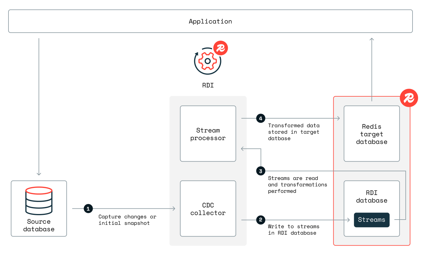
RDI synchronizes the dataset between the source and target using a data pipeline that implements several processing steps in sequence:
-
A CDC collector captures changes to the source database. RDI currently uses an open source collector called Debezium for this step.
-
The collector records the captured changes using Redis streams in the RDI database.
-
A stream processor reads data from the streams and applies any transformations that you have defined (if you don't need any custom transformations then it uses defaults). It then writes the data to the target database for your app to use.
Note that the RDI control processes run on dedicated virtual machines (VMs) outside the Redis Enterprise cluster where the target database is kept. However, RDI keeps its state and configuration data and also the change data streams in a Redis database on the same cluster as the target. The following diagram shows the pipeline steps and the path the data takes on its way from the source to the target:
When you first start RDI, the target database is empty and so all of the data in the source database is essentially "change" data. RDI collects this data in a phase called initial cache loading, which can take minutes or hours to finish, depending on the size of the source data. Once the initial cache loading is complete, there is a snapshot dataset in the target that will gradually change when new data gets captured from the source. At this point, RDI automatically enters a second phase called change streaming, where changes in the data are captured as they happen. Changes are usually added to the target within a few seconds after capture.
At-least-once delivery guarantee
RDI guarantees at-least-once delivery to the target. This means that a given change will never be lost, but it might be added to the target more than once. Apart from a slight performance overhead, adding a change multiple times is harmless because the multiple writes are idempotent (that is to say that all writes after the first one make no change to the overall state).
Checkpointing
RDI uses Redis streams to store the sequence of change events captured from the source. The events are then retrieved in order from the streams, processed, and written to the target. The stream processor uses a checkpoint mechanism to keep track of the last event in the sequence that it has successfully processed and stored. If the processor fails for any reason, it can restart from the last checkpoint and re-process any events that might not have been written to the target. This ensures that all changes are eventually recorded, even in the face of failures.
Backpressure mechanism
Sometimes, data records can get added to the streams faster than RDI can process them. This can happen if the target is slowed or disconnected or simply if the source quickly generates a lot of change data. If this continues, then the streams will eventually occupy all the available memory. When RDI detects this situation, it applies a backpressure mechanism to slow or stop the flow of incoming data. Change data is held at the source until RDI clears the backlog and has enough free memory to resume streaming.
Supported sources
RDI supports the following database sources using Debezium Server connectors:
| Database | Versions | AWS RDS Versions | GCP SQL Versions |
|---|---|---|---|
| Oracle | 19c, 21c, 23ai (LogMiner only) | 19c, 21c | - |
| MariaDB | 10.5, 11.4.x, 11.7.x | 10.4 to 10.11 | - |
| MongoDB | 6.0, 7.0, 8.0 | - | - |
| MySQL | 5.7, 8.0.x, 8.4.x, 9.0, 9.1 | 8.0.x | 8.0 |
| PostgreSQL | 10, 11, 12, 13, 14, 15, 16, 17 | 11, 12, 13, 14, 15, 16 | 15 |
| Supabase (uses PostgreSQL) | 10, 11, 12, 13, 14, 15, 16, 17 | - | - |
| SQL Server | 2017, 2019, 2022 | 2016, 2017, 2019, 2022 | 2019 |
| Spanner | - | - | All versions |
| AlloyDB for PostgreSQL | 14.2, 15.7 | - | 14.2, 15.7 |
| AWS Aurora/PostgreSQL | 15 | 15 | - |
| Neon | 14, 15, 16, 17 | - | - |
| Snowflake (preview) | - | - | - |
How RDI is deployed
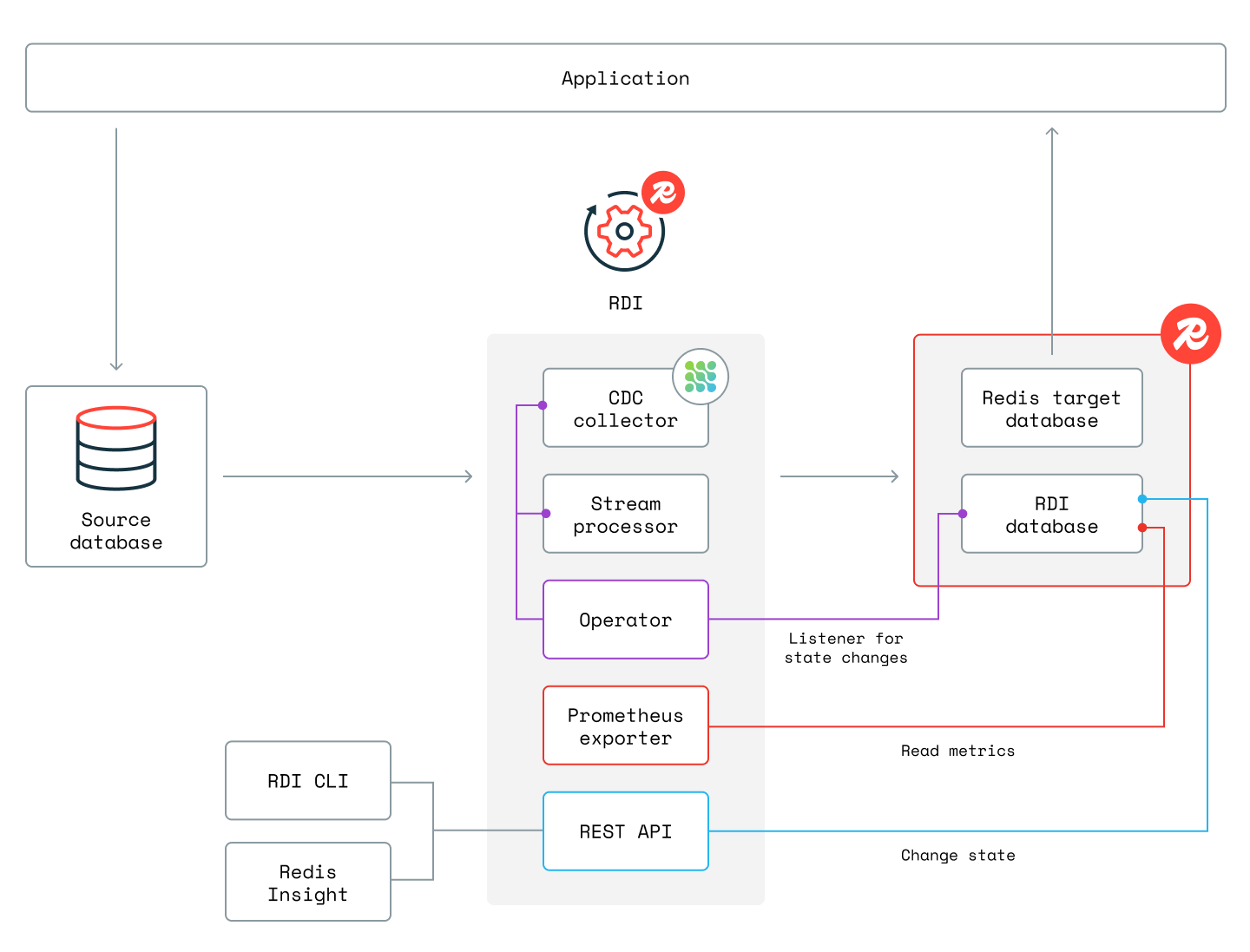
RDI is designed with three planes that provide its services.
The control plane contains the processes that keep RDI active. It includes:
- An API server process that exposes a REST API to observe and control RDI.
- An operator process that manages the data plane processes.
- A metrics exporter process that reads metrics from the RDI database and exports them as Prometheus metrics.
The data plane contains the processes that actually move the data. It includes the CDC collector and the stream processor that implement the two phases of the pipeline lifecycle (initial cache loading and change streaming).
The management plane provides tools that let you interact with the control plane.
- Use the CLI tool to install and administer RDI and to deploy and manage a pipeline.
- Use the pipeline editor included in Redis Insight to design or edit a pipeline.
The diagram below shows all RDI components and the interactions between them:
Stream processor implementations
RDI provides two implementations of the stream processor, classic and
Flink. You select the implementation per pipeline through the
processors.type
property in config.yaml. The default is classic, so existing pipelines
keep their behavior unchanged.
See Differences between the classic and Flink processors for a side-by-side comparison and Migrate from the classic processor to the Flink processor for guidance on migrating an existing pipeline to the Flink processor.
VM and Kubernetes deployments
The following sections describe the VM configurations you can use to deploy RDI.
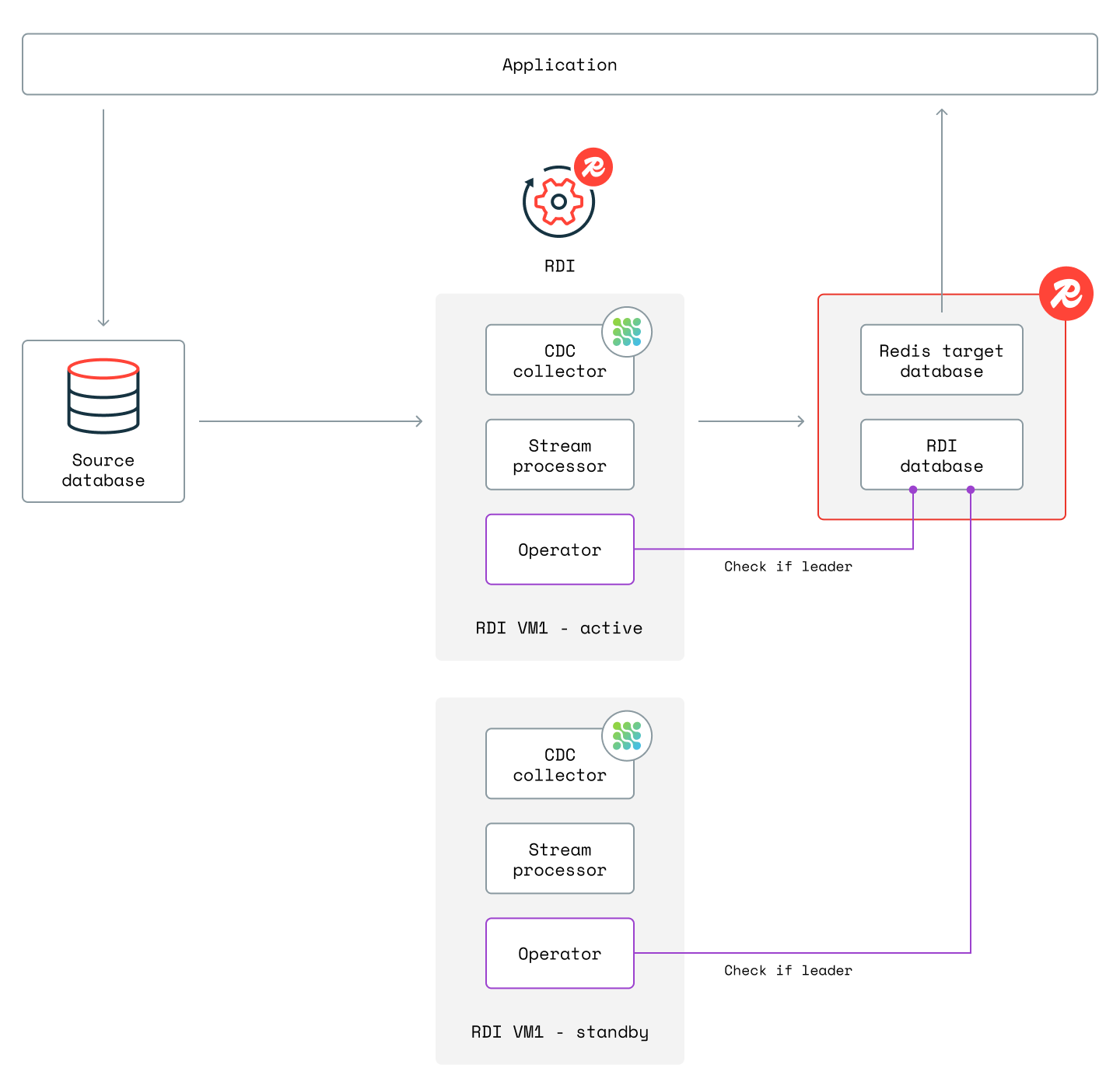
RDI on your own VMs
For this deployment, you must provide two VMs. The collector and stream processor are active on one VM, while on the other they are in standby to provide high availability. The two operators running on both VMs use a leader election algorithm to decide which VM is the active one (the "leader"). The diagram below shows this configuration:
See Install on VMs for more information.
RDI on Kubernetes
You can use the RDI Helm chart to install on Kubernetes (K8s), including Red Hat OpenShift. This creates:
- A K8s namespace named
rdi. You can also use a different namespace name if you prefer. - Deployments and services for the RDI operator, metrics exporter, and API server.
- A service account and RBAC resources for the RDI operator.
- A ConfigMap with RDI database details.
- Secrets with the RDI database credentials and TLS certificates.
- Other optional K8s resources such as ingresses that can be enabled depending on your K8s environment and needs.
See Install on Kubernetes for more information.
Secrets and security considerations
The credentials for the database connections, as well as the certificates for TLS and mTLS are saved in K8s secrets. RDI stores all state and configuration data inside the Redis Enterprise cluster and does not store any other data on your RDI VMs or anywhere else outside the cluster.